gallo magnetix
Theory of Ops
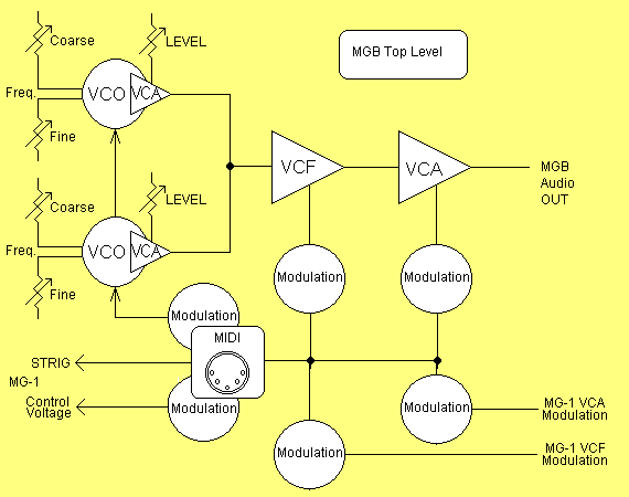
The MGB implements a MIDI controlled, Hybrid synthesizer. Audio paths are analog, envelopes and modulators are generated digitally.

MGB envelope and modulation does not model upon the MG-1. The MG-1 provides a single AR/AD envelope, and LFO/Sample and Hold. Noise is provided only for audio or source for the Sample and Hold. The MGB control capability implements a large capability for envelope, noise, and low frequency modulation sources. The capacity is great enough to not only drive MGB resident components but also those of it's companion MG-1. This results in independant envelopes for the MG-1 VCF and VCA and for additional modulation of the two MG-1 VCO's.
Operator vs Automated Control Parameterization
MGB front panel control divide into two domains; 1)the left portion of the Front Panel which presents the automation control; 2)the portion on the right which presents the real time manual operator controls.
Manual controls connect directly to MGB analog circuits and perform even would the automation "crash". MGB Automation "unifies" control of either MG-1 or MGB synthesizers for duo-phonic note assignment.
MGB Control Allocation
Upon inspection the MGB decomposes into Analog Circuits for audio generation and a bank of Digital to Analog converters which are the "portals" through which the Microcontroller and MIDI control exerts. This concept of "portals" avoids associating a specific function with a specific module connection. That is, a single DAC (which may drive a single MGB analog component) is not limited to outputing the result of a control envelope, LFO, noise, or frequency modulation source, instead any MGB control source can be summed, scaled and then output from any of the DACs. In this way all 8 of the virtual Envelopes could be "mixed" to drive a single control point such a the VCF Frequency control while a VCA might just be driven by only one of the 8 possible Envelopes.
Signal Routing
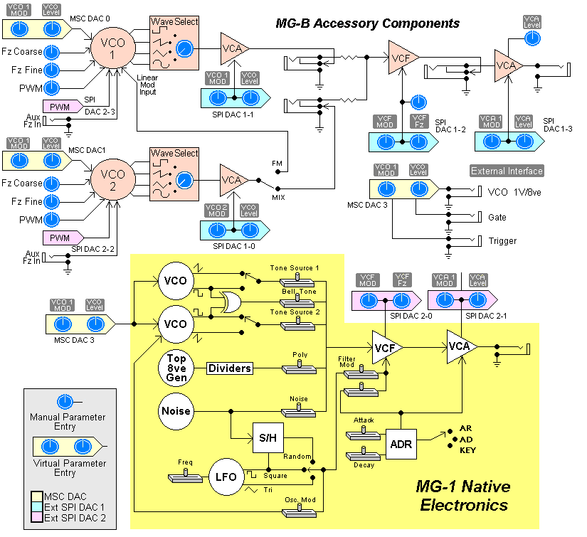
Expanding to Block Level, the following diagram depicts the companion MGB electronics, their intended routing, and technology type. This diagram depict MGB controls as either stand-alone operator controls or a virtual controls which are micro-controlled DACs which drive the components shown.

MGB architecture include;
- Two Voltage Controlled Oscillators;
- Three Voltage Controlled Amplifiers;
- A Voltage Controlled 24 dB Ladder Filter;
- Digital to Analog Convertors through which "Virtual" Modulation Sources are mixed, scaled and directed to each of the above Voltage Controlled Devices.
The MG-1 model obscures somewhat but becomes more apparent when the DACs depicted in the figure are thought of as "Virtual Pots". Also post oscillator VCA's perform as "Virtual" pre filter mixer controls.
MG-B Oscillator Characteristics
The two additional MG-B VCO's emit; Sawtooth; Triangle, PWM Square; Sine waveforms. This extends the MG waveform pallete beyond the "heavy traffic" Saw and fixed Square waveforms of the native VCO's.
Native MG-1 oscillators implement with limited independence. The MG-B VCO's are independant pitch sources each capable of performing as a LFO. Each VCO has individual Portamento and Coarse and Fine frequency control. The second oscillator can be switched to modulate the first oscillator with linear or exponential amplitude response.
Each VCO is provided a switchable linear or exponential VCA which allows dynamism for the mixing of output waveforms. Either a manual front panel control or Envelope generator controls amplitude of the VCO. Both VCA's normally route to the MG-1 VCF.
Oscillator Detail
MG-B Voltage Controlled Filter
An additional Ladder filter implements to allow "two voice" polyphony where the MGB performs as one "voice" and the MG-1 performs as the alternate voice. Patches that do not implement Polyphony can benefit from the flexibility of having two independant filters.
The MG-B ladder filter is very quiet and precise in comparison to the native MG-1 implementation.
VCF Detail
MG-B Voltage Controlled Amplifiers
In addition to the VCA's that host accessory VCO's, for pre-VCF mixing or amplitude agile FM modulation effects, two VCA's are provided which are "normally" routed to the output of the MG-1 VCF. Each is provided an separate Envelope Generator. Stereo Imaging or independant multi-channel output is available for implementation.
The MG-B VCAs are quieter and with less distortion than the native MG-1 '3080 VCA.
VCA Detail
> Additional Envelope Generators
The MG-1 provide a single, switchable, AR or AD type envelope generator. This is not untypical of some entry level synthesizers, as the JX3P also implements a single envelope generator although it is an ADSR type.
MGB augments the native MG-1 EG with 4 control voltage "channels". These control channels commit as; One 16 bit VCO control voltage being a composite of Pitch and modulation; a composite control voltage driving the VCF; another drives the MG-1 VCA; and the final channel drives the MG-1 as "general modulation" applicable for PWM, or VC resonance of the MG-1 VCF.
The MG-B orginally incorporated the MDD MIDI to Control Voltage converter. "Spec Creep" has resulted in the implementation of a more extensive MIDI/Programatic control processor. The MGB Host Processor (MHP) module provides four 16 bit, eight 8 bit, and 2 composite control voltage outputs. The implementation of the MHP provides for a high degree of synthesizer automation, primarily intended for "soft setups" or "Presets" in MIDI parlance.
Specific Information regarding the MG-B accessory circuits can be found behind the following links: