gallo magnetix
Voltage Controlled Filter
Once the MGB project grew from companion circuits to a companion synthesizer, the ability to implement duophony, or independent Note Assignment for each of the synthesizers was one obvious side effect.
To ensure maximum independence of the companion synth, an independant Voltage Controlled Filter was required for the MGB oscillators.
In keeping with the conceptual MG-1 model, the MGB VCF implements as a Moog-type Ladder Filter. While ladder filter designs abound upon the web, this specific design diverges from the MG-1 (and many alternative designs) as follows:
The physical design of the MGB VCF includes two VCA sections. One of these sections provides for Voltage Controlled Resonance, the alternate section performs as the main or Final VCA.
MGB VCF-VCA Implementation
The Final Audio Output VCA and the Voltage Controlled Resonance implement using a SSM2164 integrated circuit.

Resonance and Output VCA control voltage response is linear thanks to Mike Irwin's "servo'd linearizer".
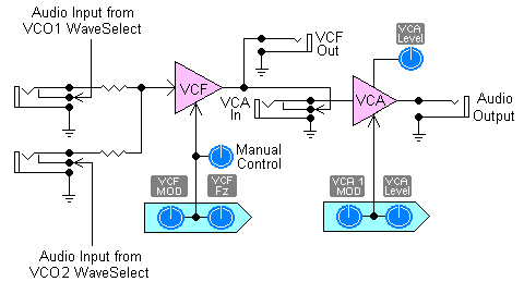
The figure left indicates the block level implementation of the VCF/VCA combination. As shown, patching is provided to allow the output of the VCF to be combined with the MG-1 VCF in addition or series configuration.
Unfiltered Audio and the output of the VCF and feed to alternate inputs of a Differential amplifier. This results in a Hi-Pass characteristic as an alternative to the typical Low-Pass output. This increases flexibility for the filter alone or in combination with the existing MG-1 filter.
MCB VCF/VCA Schematic