gallo magnetix
MIDI Interface
 MGB Panel Control:
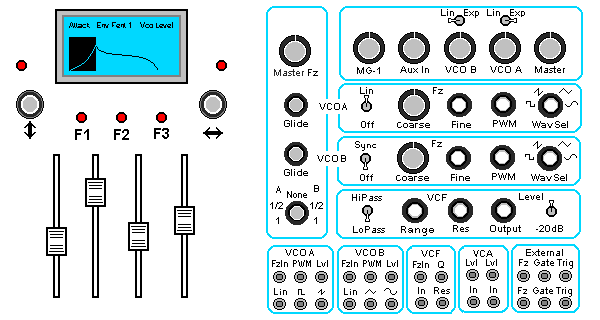
The figure left is an idealized layout for the MGB Front Panel.
Immediately noticable are the digital controls on the left with fairly conventional analog controls on the right.
Analog control perform as expected for VCO/VCF/VCA's. The Digital controls intend to operate as "intuitively". The bit mapped display attempts to graphically represent actions and parameters. Parameter entry Slide Pots are motor driven so save settings can be recalled. The Patch area provides Audio and Control inputs and outputs.
Manual Analog and Automated Digital Control:
Analog Controls on the Front Panel Right co-exist with and generally do not interface to the Digital circuitry. Remote MIDI and Voice Automation is equally "stand alone". At the patch panel the two technologies combine. If either technology failed the other would continue to operate.
Analog controls for the VCA Lin/Log switches and VCO Waveform select are interfaced to Voice Automation to allow the recall of saved "Presets".
Control Platform:
Two microcontrollers incorporate to provide the MIDI and Voice Automation with a Master/Slave configuration. Panel controls, MIDI, and the VCO Control Voltages are hosted or provided by a MSC1211 microcontroller. All envelopes and modulation sources are generated by a DS89C420 microcontroller.
Analog Control Voltages:
Pitch, Envelopes and other Modulation, can be "routed" individually or in combination to 14 Control Voltage Channels. These channels connects to conventional analog synthesizer VCO's, VCF, and VCA's.
A TI MSC1211 microcontroller, executing at 24MHz, is responsible for integrating:
A DS89C420 microcontroller, executing at 32MHz, is responsible for integrating:
The MGB panel also presents some "Event Recorder" approaches to modulations typical of "Envelope Generators" and "LFO" modulation sources, in that 128K of SRAM is devoted to "wave table control".
Standard ADSR Key or Trigger "envelopes" implement as tabled waveform "events", editable and also storeable.
The MG-B Host Processor accepts incoming MIDI messages and "maps" them to Devices.
For example, received MIDI NOTE ON/OFF messages map the message Note Value to Oscillators, Filters, (and a stored value called Note Scaling) while the "state" context (ON/OFF) "maps" to Envelope Generators and external GATE & TRIGGER ouputs.
The MG-B interfaces to a MIDI equipped Keyboard and Control Surfaces. The MIDI note range covers the entire 10 octaves that can be MIDI encoded, although the keyboard manual used may not provide for this range. The interface also allows parametric adjustment using MIDI controller messages in a generic way to allow for the widest, as well as simplest, control setting capability.
A Burr-Brown MSC-1211 EVM board exists as the core of the MIDI DAC design.
This inexpensive 8051 variant platform provides;
User Interface
The MG-B MIDI Interface is active at power up and requires no additional operator intervention for base line functionality. In this mode, the MGB is a duo-phonic synthisizer allocating 2 oscillators per each voice, a separate VCF and VCA per voice.
An integrate non-volatile preset implements a monophonic 4 VCO synthesizer. In this mode each of two VCF's is driven from the same 4 VCO "mix" but retain independant envelope control (as do their following VCA's).
Administrating the MIDI control is performed using the front panel Graphic LCD, the four Slide potentiometers, 3 switches, and two rotary Etch-Sketch "cursor" addressing controls.