|
|
|
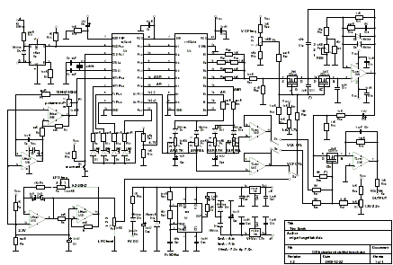
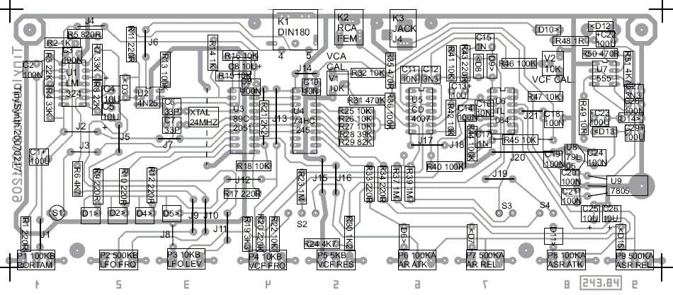
schema and technical data
The heart of the system is the old and good 89C2051 microcontroller.
There are no uncommon components at all, the integrated circuits includes operational
amplifiers LM324 an TL084, an octal buffer 74HC245, a CD4007 MOSFET dual complementary
transistor pair plus inverter, the traditional 555 and regulators 7805 and 79L05.
There are three switches for controlling the interconnection between the internal
modules. The S1 switch connects the VCF frequency control to LFO or AR signals.
The S2 switch connects the VCA to the AR envelope or left it unconnected.
The S3 switch select the VCA gain control to ASR or unconnected.
When both S2 and S3 are selected to AR and ASR positions, the result is a sum of both
signals giving similar result as ADSR envelope generator.
When both S2 and S3 are unconnected, VCA let flow the wave signal with an attenuation
of about 10dB.
 |
 |
 |
Block Diagram |
Prototype view |
Prototype view |
 |
 |
 |
Schema |
PCB |
Components |
 |
 |
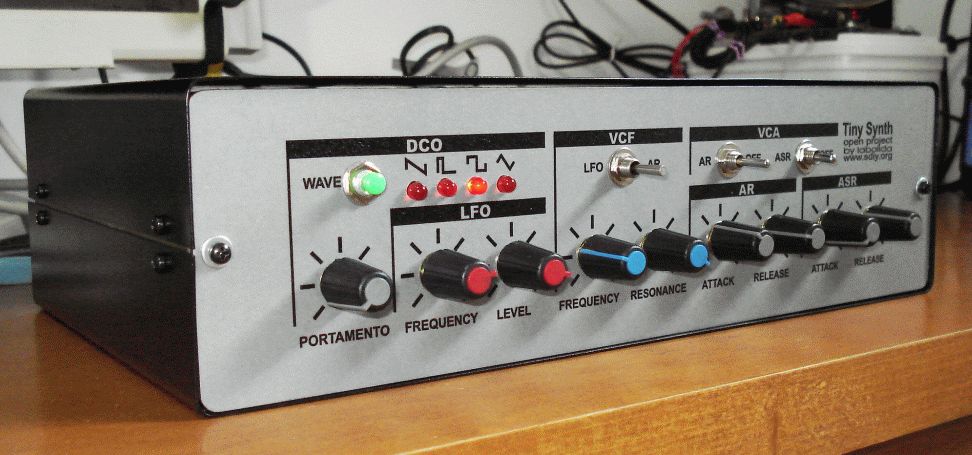 |
Front Panel |
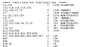
Part List |
Front view |
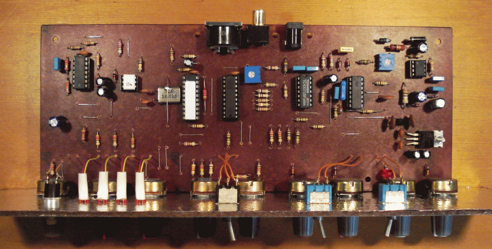
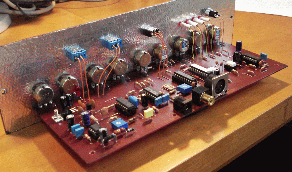
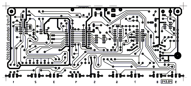
The Printed Circuit Board is single layer and includes all potentiometers and external
connectors on board, avoiding wiring.
The circuit layout maintain enough wire separation that make non critical the
construction, giving the possibility of drawing it by hand.
The source power is simply an external 9V to 12V AC/DC converter, avoiding undesired
interferences with an internal transformer. This external voltage is reduced to +5V
with a traditional 7805 regulator and created negative voltage of minus 5V with a
DC/DC converter voltage implemented with an oscillator associated to a voltage
duplicator.
DCO - Digital Controlled Oscillator
The Digital Controlled Oscillator is implemented with an AT89C2051 microcontroller,
where are processed MIDI messages, generate waveforms and envelope signals.
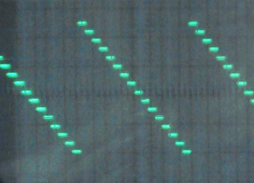
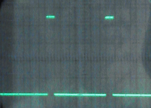
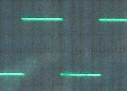
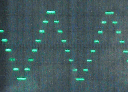
The wave has 4 bits resolution, using a passive D/A converter through resistors with
weights of 1, 2, 4, and 8.
Raw waveforms |
 |
 |
 |
 |
Sawtooth |
Pulse |
Square |
Triangle |
The glide (portamento) is obtained via software in successive halftone steps
controlled through a variable frequency oscillator.
The program was developed in C language and compiled with SDCC, Small Devices C
Compiler, available as Open Source.
The Low Frequency Oscillator sends a triangular wave that can control the VCF, with a
range of 0.2 to 20 Hz.
VCF - Voltage Controlled Filter
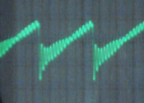
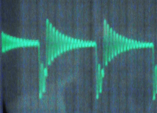
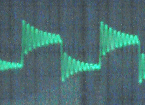
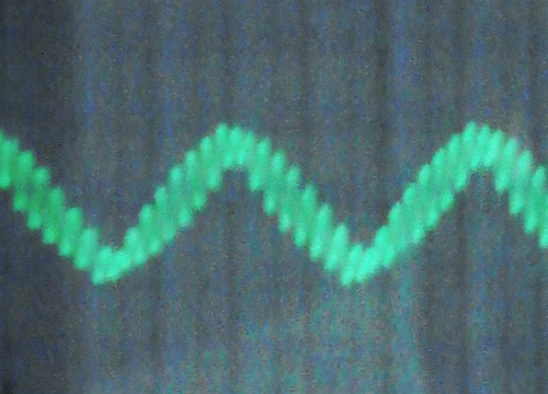
The Voltage Controlled Filter is based in the Sallen-Key structure, using MOSFET
N-channel transistors of CD4007 integrated circuit as variable resistors, to take
advantage of coupled pairs inside. The CD4007 is a MOSFET dual complementary
transistor pair plus inverter.
Filtered waveforms |
 |
 |
 |
 |
Sawtooth |
Pulse |
Square |
Triangle |
The frequency control is about 800mV per octave, in the range of 100 Hz to 5 KHz, whit
an offset of 1V approximately, depending of device used. Out of this range has a
non-exponential behavior.
The behavior of this filter is satisfactory when the linearity of control voltage is
not a critical requirement.
VCA - Voltage Controlled Amplifier
The Voltage Controlled Amplifier uses a MOSFET N-channel transistor of CD4007 as
variable input resistor in an inverter operational amplifier. A capacitor included in
the feedback path reduces the noise in high frequency band.
Envelope Generators
The AR envelope generator is done using an internal comparator of AT89C2051. At the
NOTE ON message a logic 1 signal is send to timing capacitor through an attack
potentiometer. When the comparator detects the high limit level in the capacitor, turn
the signal to logic 0. It discharges the capacitor through the release potentiometer.
The ASR envelope generator is implemented through the logic 1 signal during NOTE ON
and NOTE OFF period, charging and discharging a capacitor through attack and release
potentiometers respectively.
calibration
The calibration of VCF initial frequency is done through V2 preset that maintain a
positive bias to the gate of MOSFET transistor. This frequency must be maintained
around 10Hz in order to avoid an undesirable transition to off condition of the
transistors.
The calibration of VCF initial frequency is done through V1 preset that maintain the
bias of transistor gate in order to reaches attenuation around 80dB when te envelope
generators are inactive.
|
|