| SSM2040 Style Filter |
This module is based on the SSM2040 voltage controlled filter chip as used in some popular synths. The design here is, more specifically, based on the work by Jürgen Haible and René Schmitz. Several years ago, Jürgen Haible designed the basic filter structure which matches the block diagram in the SSM2040 data sheet. Then René Schmitz built another version with changes to the power supply configuration and a different exponential current sink. The changes included the use of a +5V reference that replaced ground in each filter stage. This allowed the current sink (bias current) to operate from ground. That version did not have the voltage controlled feedback that Jürgen Haible's did. I have started with René Schmitz' design and added Jürgen Haible's voltage controlled resonance circuit; also modified to work with the 5V reference. Other changes include: a summing opamp at the input; minor resistor changes for input, output, and feedback gain adjustments; and some new surface mounted matched transistor pairs in the discrete OTA sections.

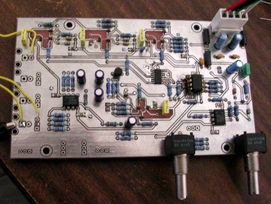
Almost finished PCB. Only needs a front panel.
The
picture above shows the mostly populated PCB of the filter I
built. Several parts on the board were replaced multiple times as I
debugged the circuit and made small adjustments to resistor values. I
ran into several problems during the construction. Most of them were
caused by bad solder points on the tiny transistor pairs (SOT-363). The
transistors used were DMMT3904W and DMMT3906W from diodes.com. These
are not reccomended for beginners. I have never had bad solder joints
working with larger parts. The difficulty is not so much in the pin
spacing (0.65mm), but in the size of the complete part. I actually had
to go out and buy a magnifying glass to read the orientation marks on
the BJT pairs. There was some talk on the Synth DIY list about
making 8pin DIP circuit boards to hold a few small surface mount BJT
pairs. I did a small layout for the discrete OTA structure used in this
filter. The OTA plus a SMD darilington buffer can easily fit on an 8pin
DIP board. I checked pricing of boards this size at Futurlec and they
would cost about $0.50 in quantities of about 20. This would be a good
approach for someone who is not comfortable soldering the small parts.
Another, easier option would be to just use hand matched BC550/560s
like the original did. I used the diodes.com pairs mostly out of
curiosity. I intended to take some measurements before building, but
they were just to small to work with unless I had made a circuit board
for this purpose.
The other SMD part (SOIC-14) is a HFA3046. This is a modern replacement for the CA3046. It is speced for high frequency and it does cost a few dolloars. I measured the matching on two of them a while back, but lost my paper that I wrote the results on. I cannot say exactly but if I remember correctly, they are comparable to the CA3046 and maybe slightly better. I have used the HFA3046 here because I had a few samples left over from some previous experiments.
The schematic diagram will be posted once I have the PCB mounted in a front panel. This might be a month or so because I would like to have panels made for several modules at once. For now, I have posted a basic analysis of the filter using linear approximations. Eventually I plan to write more about the nonlinear characteristics of the filter.
Documents:
| SSM2040 Schematic Diagram - I have not posted it here because a full testing will require installation into my modular synth. After this, If I have permission from orignal authors, I may post it. |
| SSM-2040 Analysis Part 1 - discussion and calculations for voltage-cutoff frequency relationship for a single filter stage (no resonance). This analysis uses small signal linear approximations. |
| SSM-2040 Analysis Part 2 - I intend write more about transfer function with resonance and the nonlinear characteristics that make this filter sound the way it does. |
Sounds:
nothing recorded yet. The filter sounds good, but I do not have all the input and control jacks connected yet.
nothing recorded yet. The filter sounds good, but I do not have all the input and control jacks connected yet.
| nothing recorded yet. |
| - |
Ryan Williams : 2005