 |
|
Home | Synth Modules | 9090 | Resources | Links | Contact
|
I am in the process of moving my site. the new one is not done yet, but can be found at: http://www.homebuilthardware.com
I will leave this site up for some time but probably won't see any more updates here.
This site is dedicated to the design and construction of sound synthesizers, both analog and digital. Here you will find schematic diagrams and technical information about synth building. I have several new projects in the design and/or testing phase. As time permits, I will update this site with my latest creations.
News:
06-01-2005:
Just a quick update so you know I'm still here. I have a whole lot of
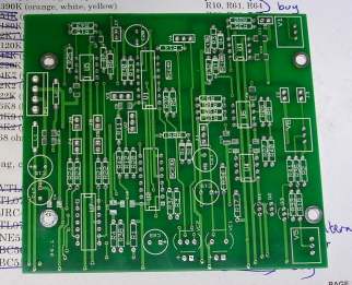
things going on, but none of them complete. Today I received a #3 Standard Wogglebug
PCB that I layed out reccently. The font panel is already here and I
just need a VTL5C3/2 before I can build it. This design is built from
Grant's schematic with only some minor changes to make the design
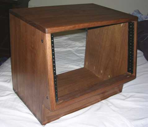
meet the requirements of my synth. #3 standard wogglebug PCB Yesterday, I received my 6U slant rack cabinet from nice-racks.
I'm very happy with this. It is so nice looking. I have come up with a
new plan for my synthesizers. I intend to buy one more of this size
rack, and two 10U straight rack cabinets. The 10U racks will hold the
modular, and the slant racks on bottom will hold things like my 9090
and probably a sequencer before too long.
My current design projects are far from complete but I'll mention one anyway. It is a mini-dsp module using a silabs 8051 w/ USB, a wavefront AL3201 dsp, and wavefront adc + dac. That dsp is quite small and only runs at 48KHz + 24bit with 2 channel I/O, but it should be enough to do the job of a single module (not variable delays though). The idea is a small and simple board that could have add-on boards to get more features. Currently I am trying to finish up a simple USB bootloader for the 8051. I have the firmware about 80% complete and am now turning my attention to the PC software to send the 8051 and AL3201 firmware. The PC software is about 30% complete. |
| 12-10-2005: I have completed a Tripple AR-AD
board. The schematic has changed from my original version so that the
minimum attack time is much shorter. I have tested one of the circuits,
but am still waiting for 1M spectrol pots and a front panel. I tested a current sink to add voltage control to the PT2399. So far I have just been checking the control voltage against the clock output frequency. With a 3mA current, I was getting about 21.5-22MHz at the clock output. This is very close to the max frequency specified in the PT2399 data sheet. I think it can go faster, but I'm not so sure it is safe to draw much more current from it. I blew a chip in the past so I am trying to be careful. This is the beginning of a new delay project. I am planning a very flexible dual delay with multiple modulation and feedback configurations. |
| 11-18-2005: I
have made some minor changes to the CMOS filter schematic that is
posted below. When I
was playing with this on the breadboard, I managed to short some
outputs (I think) and burned a 4069. When I replaced that chip, the
filter no
longer self-oscillated. I have now tried a few different ICs from
different manufactures. Each of them was noticeably different in this
circuit. With an increased gain resistor in the feedback circuit, the
filter can now self-oscillate with any of the 4069s that I have. Also,
this
allows some interesting sounds at low cutoff. The feedback circuit is
crucial, changing any of these values (besides R7) will have a pretty
big impact on the sound. Decreasing R7 will reduce the resonance range,
but may also prevent self-oscillation. 20K through 27K seems like a
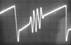
good value for R7. The oscilloscope plot below shows what happens when the filter is overdriven. The input is a sawtooth. It is ringing in the center of the rising sawtooth As the signal increases, the ringing moves away from the sawtooth reset point. So the feedback is gain dependent. With large inputs, like +-5V square waves, there is very little feedback heard. With large signal levels, a pair of beating oscillators will result in resonant beats as well.  |
| 11-02-2005: I have just finished building a CMOS version of René Schmitz'
late MS20 filter. The opamps were replaced by 4069UBE inverters. The
CA3080s were replaced with an LM13700. The cirucit structure is the
same, but some reconfiguring had to be done to account for only having
inverting amplifiers. I have no idea what an MS20 filter sounds like. I doubt this is very much like it. Check the link below for some example sweeps. The first sweep is medium resonance, the second is high resonance, and the third is overdriven. Inputs of greater than about +-2V cause the feedback circuit to slightly change its behavior. The recording has a little clipping on the last sweep; oops. cmos ms-20 filter sweeps If anyone reading this has built René's MS20 filter clone, then I would like to know how this one compares. Do the inverters have much effect? Check the link below for the schematic. The current source used is a super simple *linear* current source. René's expo source from the original would be better if this was going into a module. I intend to add this to a theremin project that I am working on; more on that later. cmos ms-20 filter schematic |
| 10-26-2005: An AR/AD Transient Generator has been built and tested. |
| 10-25-2005: SSM-2040 filter page has been updated.s |
| 09-17-2005 : The VC-Echo page has been updated with plans for future development. |
| 09-16-2005 : New website is up. |
Webspace was provided by tom @ www.sdiy.org. thanks!
Ryan Williams : 2005
