| Frequency Shifter |
This project is a single channel frequency shifter inspired by Jürgen Haible's design(1 and 2). This circuit is basically a single sideband modulator that operates in the audio range. It will allow up and down shift at the same time with the ability to shift into negative frequencies. The multiplier circuit is based on JH's design (somewhat different now) and the Dome Filter is an exact copy (originally from Electronotes). The main difference is in the quadrature oscillator. I have decided to build a digital oscillator.
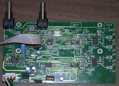
This is an on going project and it will most likely be a while before the entire circuit is built and tested. This is mostly due to lack of time and that I have several other synth projects I'm working on. Currently, I have the oscillator completed on one circuit board. The Dome Filter and Multipliers will go on a seperate board. The initial design for the filter and multipliers are finished but need to be tested on the breadboard before I invest in a nice PCB.
Quadrature Oscillator
Dome Filter
Multipliers
Quadrature Oscillator:
I reccently worked on a 75MHz band FM transmitter and reciever in a school project lab course. An Analog Devices Direct Digital Synthesizer (DDS) was used for frequency synthesis. I had a couple of ICs left over, so I am putting them to use in this project. If everyting works out properly, I may design another digital oscillator board with the NCO programmed into an Atmel AVR, or maybe it could be done with one of those new Atmel FPSLICs (AVR with FPGA).

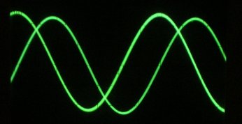
Two DDS ICs are used to generate sin and cos functions. These DDSs are clocked at 1MHz (which is the minimum speced clock rate in the data sheet). These parts have 10-bit DACs. A negative frequency is generated by reversing the direction (subtracting instead of adding) of the phase accumulator in the DDS. The frequency is controlled by an Atmel Atmega8 microcontroller. A high speed 16-bit ADC is used for voltage control. The maxium output frequency of the oscillator is currently at about 1.95KHz. I may change this to 3.9KHz depending on what resolution I decide is reasonable. The maximum modulation rate is currently around 5KHz. I think it will work ok for the frequency shifter.

sine and cosine output from the oscillator board
The 2 DDS ICs are very expensive ($20 each). I'm only using them because I have them and already know how to use them. About half of the board uses surface mount components. This saves PCB space (which equals cost) and the design is only 5.5" x 3.05". the Atmega8, 2 AD9850 DDS chips and supporting circuitry, the 16bit ADC, as well as most of the bypass capacitors are all surface mount. I have limited experience working with these tiny parts although after soldering many circuit boards for the school project, I think I've got it down. It is not that difficult for some of the larger packages (like 1206 passive components). It does take a little practice and a deccent soldering iron, but so does through hole.
The dome filter I am building is directly from the schematic on Jürgen Haible's website. I do not have much to say about it but I will put up some pictures when it is done.
I have changed some things from Jürgen Haible's multiplier section. The circuit is fairly straight forward. It uses two AD633 multiplier ICs plus a few opamps for input gain, output gain, and sum and difference amplifiers. I have added two THAT2180 VCAs for voltage control of up shift and down shift feedback (that should be interesting). The initial circuit design is finished but I need to do some testing before actually building the whole thing. Initially, I am going to leave off the noise reduction companding circuit. After building the multiplier on a breadboard, I will decide if it is necessary.
Ryan Williams : 2005