BINDUBBA 1 SEQUENCER
This circuit is a crossbreed of the concept of an Analog Shift Register and a CGS Sequential Switch.
Basically it is a 4 stage sequencer. If the pots are labelled ABCD, the outputs will emit voltages in the patterns of ABCD, BCDA, CDAB, DABC and in the reverse direction; DCBA, CBAD, BADC, ADCB.
This means you can have a 4 stage ditty driving one VCO and the exact reverse of that ditty running another, or the reverse staggered by one clock pulse...or two clock pulses....etc.
Just to suck it dry, there are inverse outputs available too, and I couldn't let the extra stages of the 4024 chip be idle, they are connected to a R2R ladder to give a staircase output (and its inverse).
In the schematic, P1 connects to the wipers of four 100k pots wired as voltage dividers. These could also go to jacks to route CV signals, but extra components would be required to ensure no negative voltages are introduced to the 4052 chips.
Some of the function blocks, such as the clock and reset subcircuits, output buffers and R2R section, are copied straight from CGS circuits. Most of my modules are CGS so it makes sense to design this module to conform to those standards.
Function Block description:
A 4024 ripple counter is driven by a clock signal obtained from a comparator sub-circuit and can be reset by a pulse to the appropriate jack. The clock signal can be any rising edge crossing approx 1.5V.
Q1 and Q2 from the 4024 are connected to the control inputs of four 4052 dual 4 channel mux/demux chips. These all switch the four inputs to the output in the order of X1, X2, X3, X4 for each section.
Four pots wired as voltage dividers provide the set voltages to the inputs of the 4052s. The way each section is connected determines the start point and direction of each 4 step sequence.
Each 4052 output is connected to a voltage buffer sub-circuit which supplies the output sequence and its inverse.
As mentioned above, the extra outputs of the 4024 are connected to a R2R ladder and then a similar output buffer sub-circuit to provide a staircase output and (of course!) its inverse.
bindubba1 pdf [vers.3](1050kB)
bindubba1 early Serge style panel design (157kB)
bindubba1 build notes 14/4/2010 (updated 5/2/2012)(73kB)
plots showing output voltages (18kB)
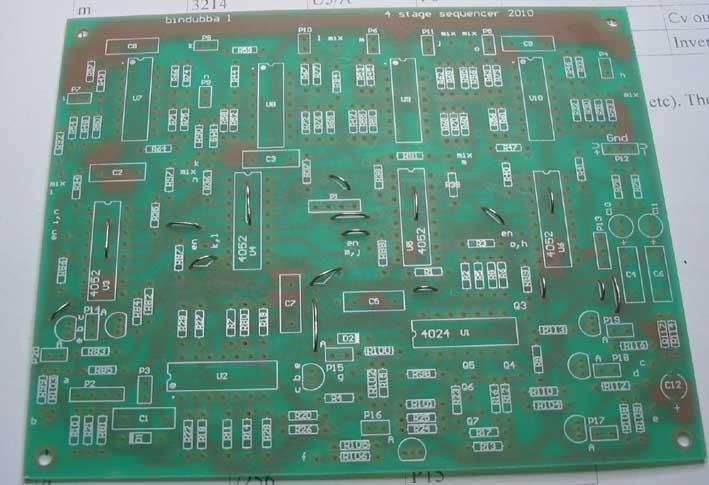
don't forget to install links before the ICs!!
Test #1 was thwarted by the discovery that a MC4024 is not a 7 bit ripple counter. gotta go shopping.
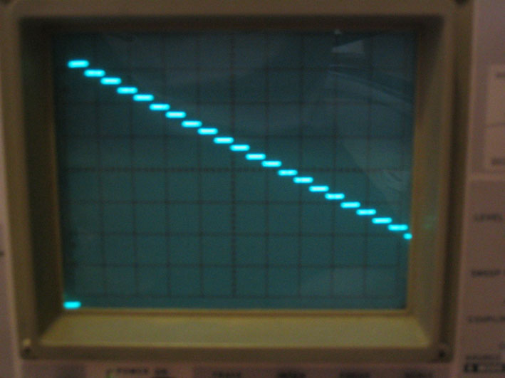
staircase output
Not a great demo, just using the camera's mic, so scratchy sound
These demos were made with the sequencer controlling 4 VCOs. The VCOs were connected to VCFs and wave multipliers, all CV'd by the sequencer as well. During record I just changed the song sequencing switches and the levels on the mixer.