Menu
- Home
- Pictures June 2007
- Pictures August 2007
- Samples
- Links
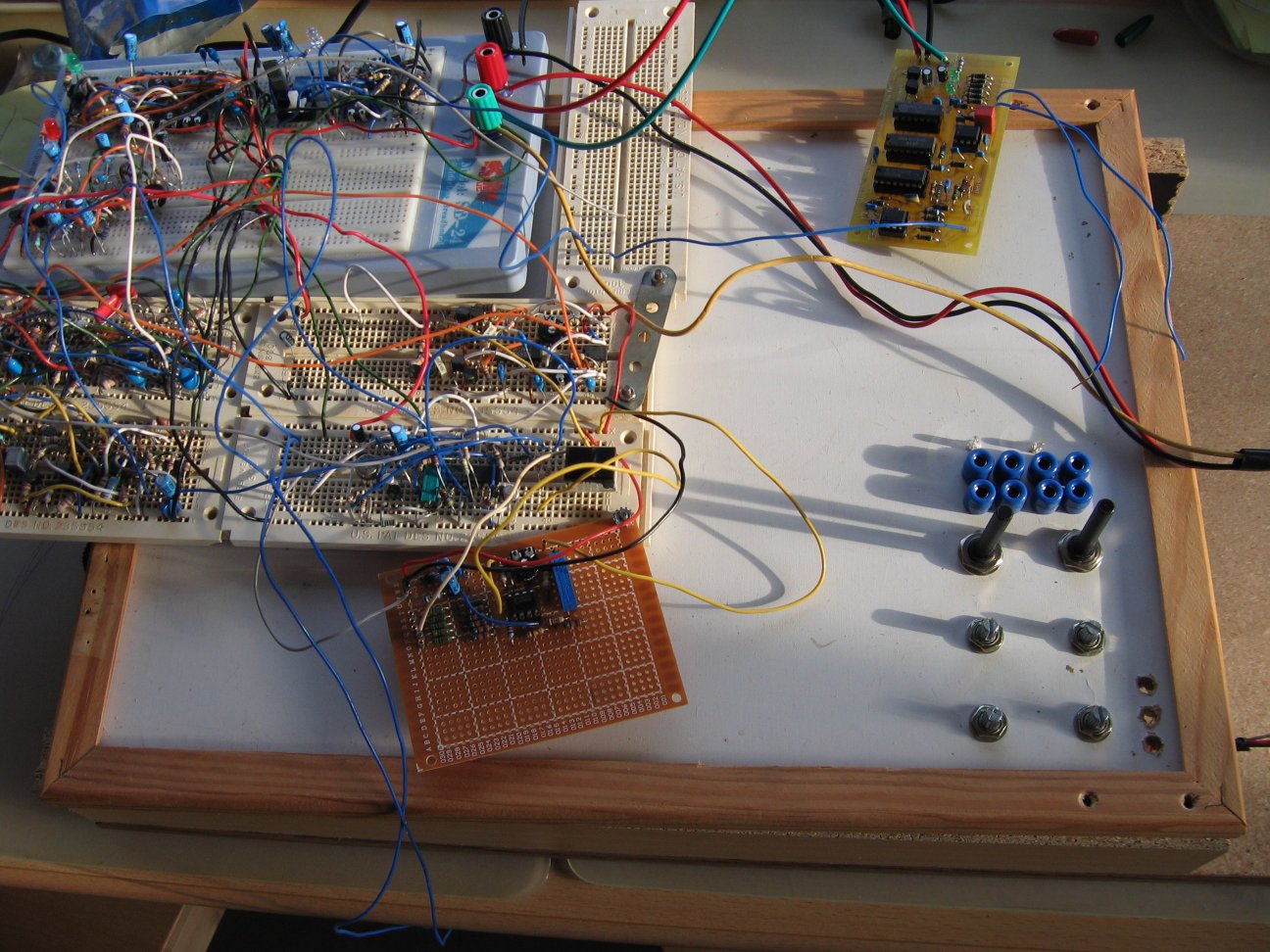
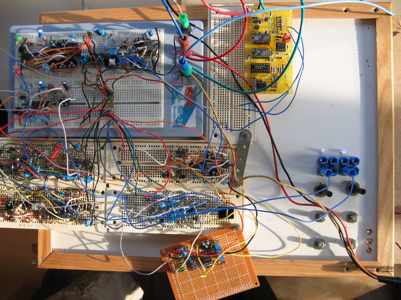
Here you have an overview of the global setup so far. On the breadboards there are still a lot of the remaining circuits (VCO's, filter, one half utility LFO, mixer, ...). There is a new (now empty) breadboard that contained a noise generator (Ken Stone's CGS31) but this one is now hard-soldered on a PCB I ordered from Ken. I also started building stuff inside a kind of wooden box so that it is easier to mount pots. At this moment only the utility LFO is there. You can see more detailed shots of the utility LFO and digital noise generator below. The small keyboard I had last time is now gone because I accidently burned the 74C923 chip that is rather essential for its operations. I have yet to find a replacement for that.
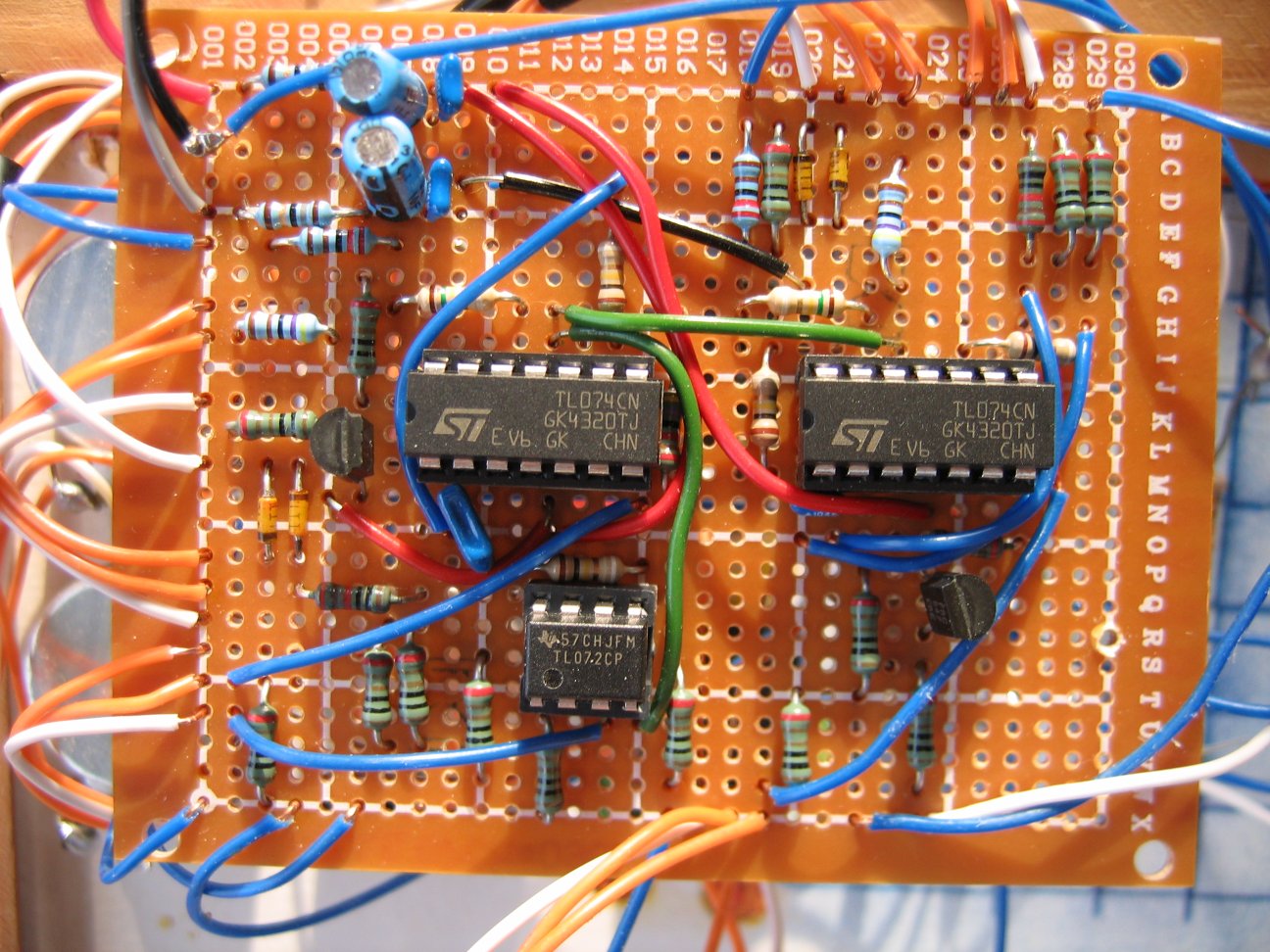
This is part of the mini keyboard (CGS10) that I built on a rasterboard. Conveniently hidden by the black cable you just cannot see the burned out 18 ohm resistor which after being burned out still operates as a 7 ohm one. The thing that happened is that the grey -12V cable accidently disconnected and touched the +12V resistor at the wrong side. Thus causing full 24V over the poor 18 ohm resistor. The 74C923 on the keyboard rasterboard also blew but surprisingly nothing else. Even the caps and the TL072 on this rasterboard survived the temporary reversal from +12V to -12V.
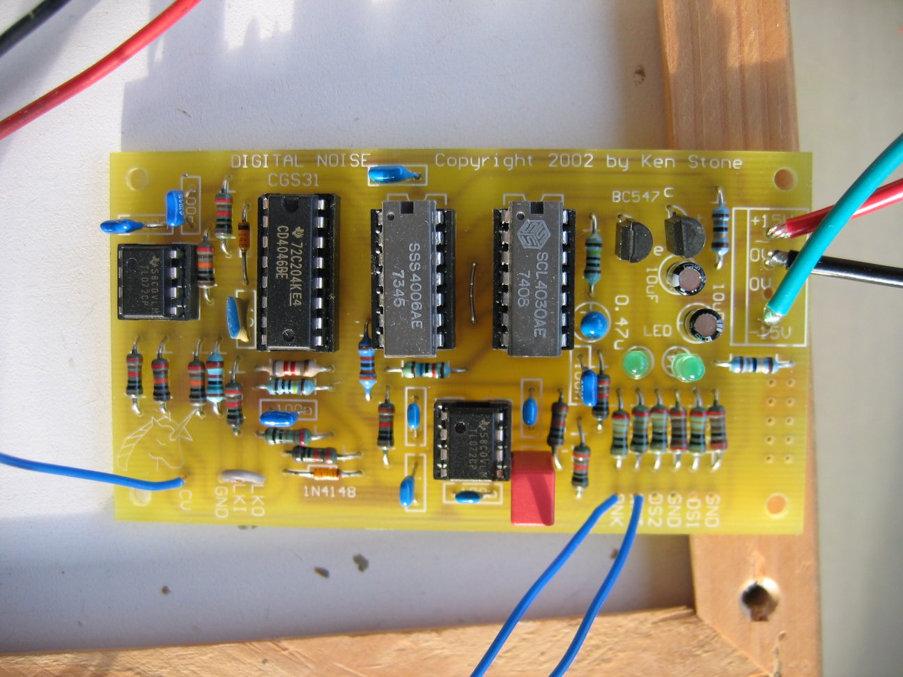
I ordered a digital noise generator PCB (Ken Stone's CGS31). It is operating nicely. I also ordered a few more PCB's but I haven't soldered those yet.
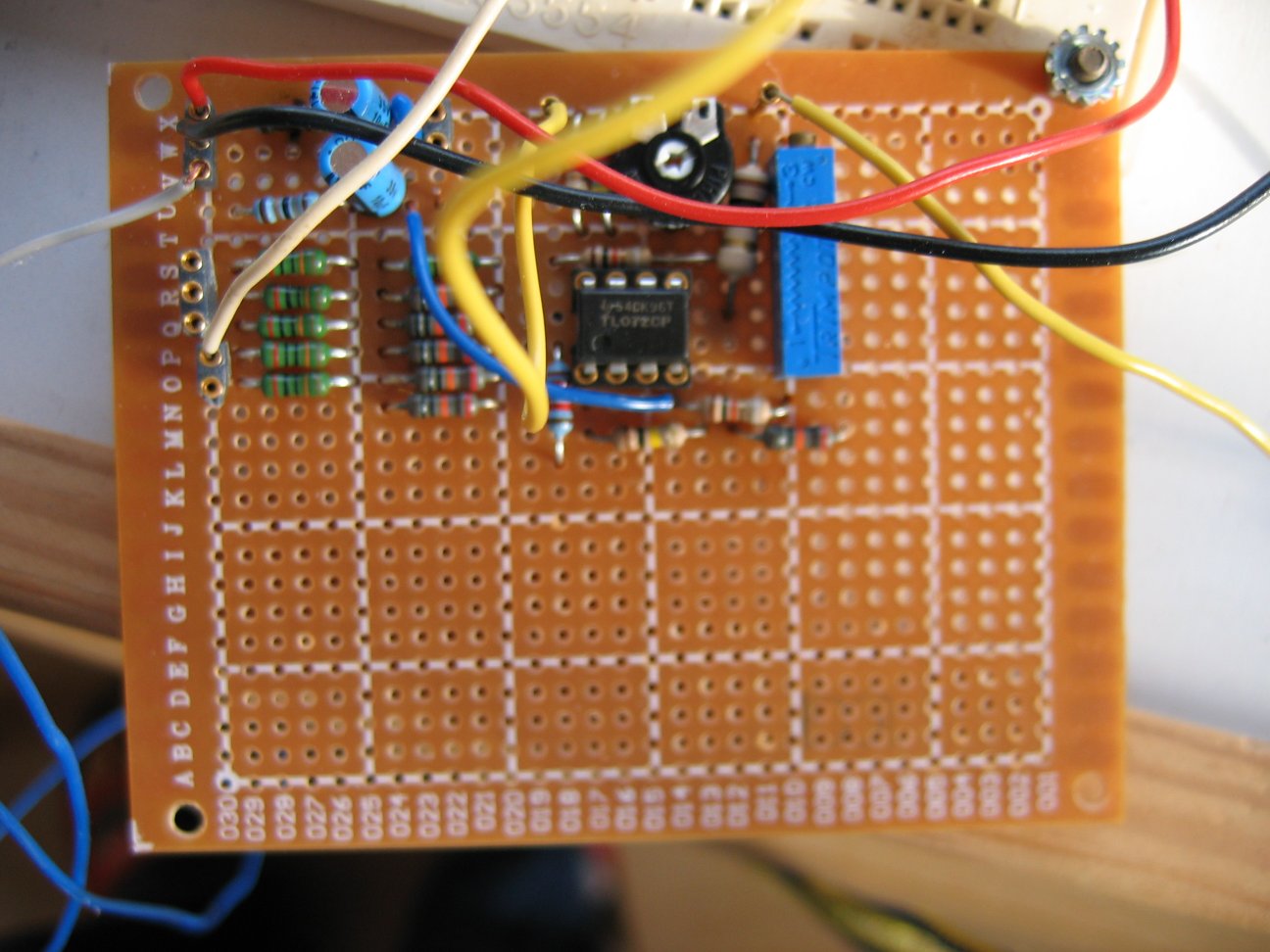
Here you see the utility LFO that I made myself on my own rasterboard. I was very surprised that it worked from the first start. It was not easy to create given that I had to make all connections at the back by using excess wires of the components themselves.